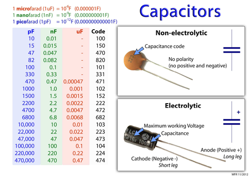
Here is my complete conversion chart for all standard capacitor values. This chart allows one to convert between picofarads, nanofarads, and microfarads. With all the values listed here, you will not have any need to use a calculator.
Ceramic disc capacitor code / label will normally consist of three numbers followed by a letter. They are very easy to decode to find the value. The first two significant digits represent the first two digits of the actual value, which is 47. The third digit is the multiplier, which is ×1000. The letter J signifies the tolerance of ±5 %. Since this is the EIA coding system, the value will be in pico farads. Hence the value of the capacitor above is 47000 pF ±5 %.
- This calculator converts capacitance value between units pF, nF, µF and F. The capacitor code conversion chart lets you find the capacitance by looking up the code. The first two digits are the value in picofarads, while the third is the multiplier. If no multiplier is given the result is capacitance in pF.
- Monolithic Capacitor These non-polar capacitors have equal length leads that can be installed in either direction and come in many colors. The chart illustrates how to determine their value using the three-number and letter code found on most monolithic capacitors. General Capacitor Codebreaker.
- Usually the first two digits of the code represent part of the value; the third digit corresponds to the number of zeros to be added to the first two digits. This is the value in pf. General Capacitance Codebreaker Charts pico-farad (pF) nano-farad (nF) micro-farad (mF,uF or mfd) capacitance code 1000 1 or 1n 0.001 102.

A ceramic disc capacitor does not have a polarity and connects in any direction on the printed circuit board. If you are new to capacitor codes, then the best way to start is with a chart, because that way, you can see the arrangement of the code. Engineers usually do not require calculators because the code is so simple. Here is another example, code 104 is 10 followed by four zeros, hence 10 0000 pF. As you can see, it is so easy that you can do this in your head.
How to read Capacitor Codes
| 1st Digit | 2nd Digit | 3rd Digit (Multiplier ×) | Tolerance Letter | ||
| 0 | 0 | 0 | ×1 | C | ±0.25 pF |
| 1 | 1 | 1 | ×10 | D | ±0.5 pF |
| 2 | 2 | 2 | ×100 | E | ±1 pF |
| 3 | 3 | 3 | ×1000 | G | ±2 % |
| 4 | 4 | 4 | ×10000 | J | ±5 % |
| 5 | 5 | 5 | ×100000 | K | ±10 % |
| 6 | 6 | 6 | ×1000000 | L | ±15 % |
| 7 | 7 | 7 | ×10000000 | M | ±20 % |
| 8 | 8 | 8 | ×100000000 | N | ±30 % |
| 9 | 9 | 9 | ×1000000000 | Z | +80 % to 20% |
EXAMPLES: If a capacitor is marked 103J, its value is 10,000 pF ±5 %. If a capacitor is marked 335K, its value is 3300000 pF ±10 %

Standard Capacitor Values
| 1 pF | 82 pF | 2500 pF |
| 1.8 pF | 100 pF | 2700 pF |
| 2.2 pF | 120 pF | 3000 pF |
| 2.7 pF | 150 pF | 3300 pF |
| 3 pF | 180 pF | 3900 pF |
| 3.3 pF | 190 pF | 4000 pF |
| 3.9 pF | 200 pF | 4700 pF |
| 4.7 pF | 220 pF | 5000 pF |
| 5 pF | 250 pF | 5600 pF |
| 5.6 pF | 270 pF | 6800 pF |
| 6.8 pF | 300 pF | 8200 pF |
| 8.2 pF | 330 pF | 10000 pF |
| 10 pF | 390 pF | 20000 pF |
| 12 pF | 470 pF | 22000 pF |
| 15 pF | 500 pF | 30000 pF |
| 18 pF | 560 pF | 47000 pF |
| 20 pF | 700 pF | 50000 pF |
| 22 pF | 750 pF | 0.1 µF |
| 27 pF | 820 pF | 0.666 µF |
| 30 pF | 1000 pF | |
| 33 pF | 1200 pF | |
| 39 pF | 1500 pF | |
| 47 pF | 1700 pF | |
| 50 pF | 1800 pF | |
| 56 pF | 2000 pF | |
| 68 pF | 2200 pF |
Here is a list of the currently available ceramic disc capacitors consisting of standard values. Large electronics suppliers will tend to stock all of these.
Voltage Code
The brown coloured ones usually have an underline below the marking, which means 50 V / 100 V. If there is no underline, then the rating is 500 V, assuming the manufacturer follows the marking scheme.
The epoxy-coated capacitors usually have the letters 1KV, which indicates 1000 V, and 2KV indicating 2000 V.
Sometimes capacitors do not have any markings regarding voltage rating and you have to look up the documentation of that component. However, manufacturers often use a combination of the above marking scheme.

Temperature Code
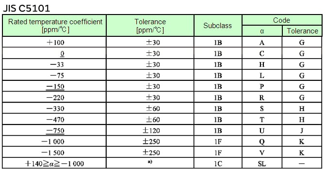
The black mark at the top of the disc represents the operating temperature range, which is approximately -25-°C to +85-°C.
Replacement
Ceramic disc capacitors come in many versions. For basic general applications, the brown ones are usually utilised for decoupling in low voltage circuits.
For switched-mode power supply applications, epoxy coated flame retardant capacitors are usually used. These meet the UL 94-V0 standard. They were originally utilised in the line-output stages of conventionalCRT based television sets.
This Article Continues...
Ceramic Disc Capacitor Values / Code / LabelCeramic Capacitors in Parallel Calculator
Ceramic Capacitors in Series Calculator
Non-Polarised Capacitor Symbol
pico nano micro milli kilo mega giga tera
